- Call : (022)- 35346924 / (022)-35346932
- Email : info@dpminstrument.com
Indicators
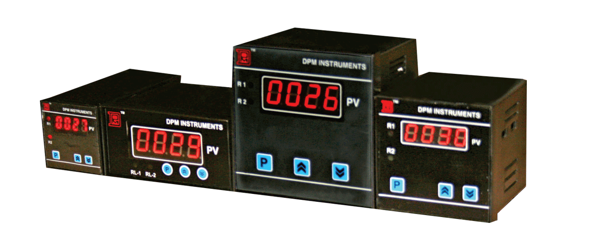
Temperature Indicators
Capacitance level indicator Utilizes the capacitance formed between the sensing probe and the metallic vessel wall. A high frequency sine-wave is applied between the probe and the vessel wall. A change of the medium level will induce a change in the current of the applied sine-wave. From Z.Y..fact, when the capacitance in the vessel increase, impedance will decrease and anent will increase. Vice-versa, when the capacitance in the vessel is small, the impedance will increase and current will decrease accordingly.
Features :
- Suitable for high temperature, high pressure and comssive environment
- Not affected by noisy, dusty, misty and changes in the temperature.
- No blind distance, ideal fordifferenttanks
- Economical for large tanks
- 4-20mAoutput compatible for mostcontrol systems and meters.
Ordering Information:
| Modal | Input | Retransmission(4 to 20 mA) | Panel Cutout | Dimensions | Manual | Specifications |
|---|---|---|---|---|---|---|
| IT-603 | Specify | optional | 90 x 90 mm | 96 x 96 x 110 mm | Download | Download |
| IT-603/2 | Specify | optional | 90 x 90 mm | 96 x 96 x 110 mm | Download | Download |
| IT-603/3/6 | Specify | ------ | 90 x 90 mm | 96 x 96 x 110 mm | Download | Download |
| IT-72 | Specify | ------ | 68 x 68 mm | 72 x 72 x 110 mm | Download | Download |
RPM Indicators
Ordering Information:
| Modal | Input | Retransmission(4 to 20 mA) | Panel Cutout | Dimensions | Manual | Specifications |
|---|---|---|---|---|---|---|
| RI-48 | Specify | ------ | 45 x 90 mm | 48 x 96 x 110 mm | Download | Download |
Process Indicators
Ordering Information:
| Modal | Input | Retransmission(4 to 20 mA) | Dimensions(size) | Manual | Specifications |
|---|---|---|---|---|---|
| PI-96/2 | Specify | ------ | 96 x 96 x 110 mm | Download | Download |
| PI-201 | Specify | ------ | 12" 6" 6" | Download | Download |
| PI-401 | Specify | ------ | 18" 7" 7" | Download | Download |